The 4-Minute Rule for Building Services Engineer
Table of ContentsWhat Does Building Services Engineer Mean?Little Known Questions About Building Services Engineer.Things about Building Services EngineerSome Known Factual Statements About Building Services Engineer All About Building Services Engineer
Whether you're a student, an educator, or a lifelong learner, Vocabulary. com can put you on the path to methodical vocabulary improvement.This section is a mostly from the viewpoint of Lagrangian dynamics. In specific, we evaluate the formulas of a string as an example of a field theory in one dimension. We begin with the like a single particle. Lagrange's equations are where the are the collaborates of the particle.
Similarly, we can specify the where are the momenta conjugate to the collaborates. For a continuous system, like a, the Lagrangian is an essential of a Lagrangian density function. For example, for a string, where is Young's modulus for the material of the string and is the mass density.
All about Building Services Engineer
For the string, this would be. Recall that the Lagrangian is a function of and its area and time derivatives. The can be computed from the Lagrangian density and is a function of the coordinate and its conjugate momentum. In this example of a string, is a. The string has a displacement at each point along it which varies as a function of time.
This is the. There are much easier ways to get to this wave formula, however, as we move far from simple mechanical systems, a formal method of proceeding will be extremely valuable. Jim Branson 2013-04-22.
Mechanical Systems Design & Analysis Engineer Los Angeles, CA Mechanical Systems Style & Analysis Engineer 10/2016 present Los Angeles, CA Mechanical Systems Style & Analysis Engineer 10/2016 present Supports system elements' designs/proposals standards to offer installation and information documentationTrains othersDetermine and establish approaches to solutionsDevelop, file, and keep procedures, techniques, and toolsHelp resolve programmatic and technical issues that would affect cost, schedule, and performanceDevelop and analyze drawings, information sets, reports, and specificationsSupports the development, maintenance or adjustment of system, component and setup designs/proposals to provide design documentation to downstream groups.
Building Services Engineer for Beginners
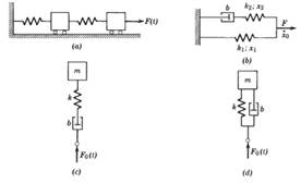
If you are more familiar with mechanical systems, this example might assist enhance a few of the principles we have actually covered so far. The system we want to model is the one displayed in the following figure: It deserves explaining how much easier it is to convey the objective of a design by presenting it in schematic form.
While we are currently concentrating on equations and variables, we will ultimately work our way approximately an approach (in the upcoming section of the book on Parts) where. For now, however, we will concentrate on how to express the formulas related to this simple mechanical system. Each inertia has a rotational position, varphi, and a rotational speed, omega where omega = dot varphi.
Building Services Engineer for Beginners

Pulling all of these variables and formulas together, we can express this problem in Modelica as follows: design SecondOrderSystem "A 2nd order rotational system" type Angle= Real( find here system=" rad"); type AngularVelocity= Real( system=" rad/s"); type Inertia= Genuine( unit=" kg. m2"); type Stiffness= Genuine( system=" N.m/ rad"); type Damping= Real( system=" N.m. s/rad"); parameter Inertia J1= 0. 4 "Minute of inertia for inertia 1"; criterion Inertia J2= 1. 0 "Minute of inertia for inertia 2"; criterion Tightness c1= 11 "Spring constant for spring 1"; criterion Tightness c2= 5 "Spring consistent for spring 2"; criterion Damping d1= 0.
0 "Damping for damper 2"; Angle phi1 "Angle for inertia 1"; Angle phi2 "Angle for inertia 2"; AngularVelocity omega1 "Velocity of inertia 1"; AngularVelocity omega2 "Speed of inertia 2"; initial equation phi1 = 0; phi2 = 1; omega1 = 0; omega2 = 0; formula// Formulas for inertia 1 omega1 = you could try here der( phi1); J1 * der( omega1) = c1 *( phi2-phi1)+ d1 * der( phi2-phi1);// Formulas for inertia 2 omega2 = der( phi2); J2 * der( omega2) = c1 *( phi1-phi2)+ d1 * der( phi1-phi2)- c2 * phi2-d2 * der( phi2); end SecondOrderSystem; As we finished with the low-pass filter example, RLC1, let's stroll through this line by line.
m2"); type Tightness= Real( system=" N.m/ rad"); type Damping= Genuine( unit=" N.m. s/rad"); Then we define the numerous parameters used to represent the various physical characteristics of our system: criterion Inertia J1= 0. 4 "Moment of inertia for inertia 1"; specification Inertia J2= 1. 0 "Moment of inertia for inertia 2"; parameter Tightness c1= 11 "Spring constant for spring 1"; criterion Stiffness c2= 5 "Spring consistent for spring 2"; criterion Damping d1= 0.
Some Known Factual Statements About Building Services Engineer
0 "Damping for damper 2"; For this system, there are four non-parameter variables. These are specified as follows: Angle phi1 "Angle for inertia 1"; Angle phi2 "Angle for inertia 2"; AngularVelocity omega1 "Velocity of inertia 1"; AngularVelocity omega2 "Velocity of inertia 2"; The preliminary conditions (which we will revisit soon) are then defined with: preliminary equation phi1 = 0; phi2 = 1; omega1 = 0; omega2 = 0; Then come the equations describing the vibrant response of our system: formula// Equations for inertia 1 omega1 = der( phi1); J1 * der( omega1) = c1 *( phi2-phi1)+ d1 * der( phi2-phi1);// Equations for inertia 2 omega2 = der( phi2); J2 * der( omega2) = c1 *( phi1-phi2)+ d1 * der( phi1-phi2)- c2 * phi2-d2 * der( phi2); And lastly, we have the closing of our design definition - building services engineer.
This indicates that we will be unable to define any alternative set of initial conditions for this model. We can conquer this concern, as we made with our Newton cooling examples, by specifying parameter variables to represent the preliminary conditions as follows: design SecondOrderSystemInitParams "A 2nd order rotational system with initialization specifications" type Angle= Genuine( unit=" rad"); type AngularVelocity= Genuine( system=" rad/s"); type Inertia= Genuine( unit=" kg - building services engineer.